EN

CN Ru

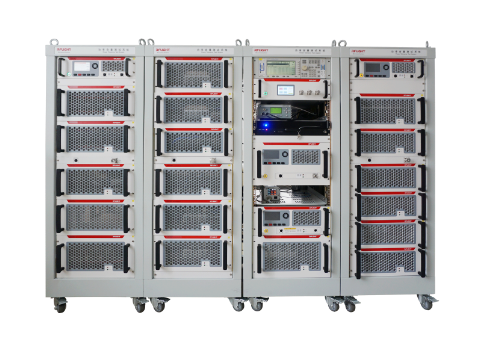
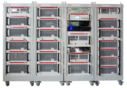
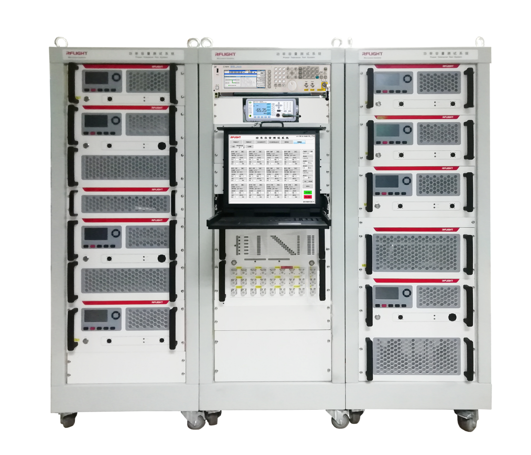
Power tolerance test system

Power tolerance test system

Summarize

The power tolerance test is to test the maximum tolerance of the component for the heat energy caused by the maximum input signal without causing problem interference. It is an important detection technology mainly used to test the design and manufacturing of passive devices. It determines whether the performance of the device deteriorates after the RF signal is amplified by the power amplifier (mainly the standing wave performance) to determine the peak power performance of the device. The increasing high power makes the passive device bear more and more heavy power load, so the probability of system interference is constantly increasing. In order to ensure the communication capability of the system and the demand of the call quality, and reduce the system interference from the source, it is necessary to carry out power tolerance test for the passive device.

Product Description Technical indicators

Application Scenario

Rf component power HTOL test, as a harsh stress test, verifies the operating life of the device by simulating aging and power load acceleration excitation failure, has been widely used in ceramic/dielectric filters, isolators, attenuators, resistors and other reliability tests.


Product features:

System frequency range up to 1 ~ 40GHz (extensible)
Simultaneous test up to 12 channels (scalable)
Power capacity up to 10kW (scalable)
High precision power control: ±0.1dB
High precision temperature monitoring: ±0.2°
High stability operation: 1000h operation
Graphical User Interface Control (GUI)
Compact 19-inch cabinet design

Product Characteristics

The test band can cover 698 MHz to 2700 MHz
Support continuous wave, pulse wave, modulated signal power tolerance test
EGSM, CDMA, WCDMA, LTE and other modulation signals are supported
Multi-carrier input is supported
Flexible combinations
High reliability design to meet the needs of uninterrupted use
Through software control, it is easy to realize the power tolerance test and fly-arc test of the tested part, and can automatically store the test data and form the test report
Average power: +40 dBm ~ +60 dBm(1kW)
Peak power: +40 dBm ~ +70 dBm (10kW)

Main technical parameters

System configuration:

name

model

description

signal generator

N5173B

Analog signal source, 9 kHz-40GHz, including step attenuator, analog modulation, pulse modulation, and cabinet mounting parts

Power meter host

N1914A

Dual channel power meter

Power meter probe

E9304A

10 kHz-6GHz, -60 dBm to + 20 dBm

Power meter probe

L2054XA

Mean power probe, 10 MHz-40GHz, -70~ + 20 dBm power probe

Power amplifier group

NTWPA-XXX

Customized power amplifier set according to customer frequency and power requirements