Power Amplifier
High Intensity Radiation Field (HIRF) system
Electronic warfare simulation system
Intermodulation test system
Rf matrix system
Microwave active module
Passive device
Product Center
Conducted immunity test system
Summarize
Conducted immunity test items are used to verify the ability of the device under test (EUT) to withstand RF signals coupled to EUT-related cables and power supplies. Interference by injection probes is required in the EUT harness, the EUT should not experience any failure, performance degradation, or deviation from specified indicator values, or exceed the indicator tolerances given in the specifications for individual devices and subsystems. In many of today's military customers, it has long been labeled as a must-check for military EMC testing.
Application Scenario
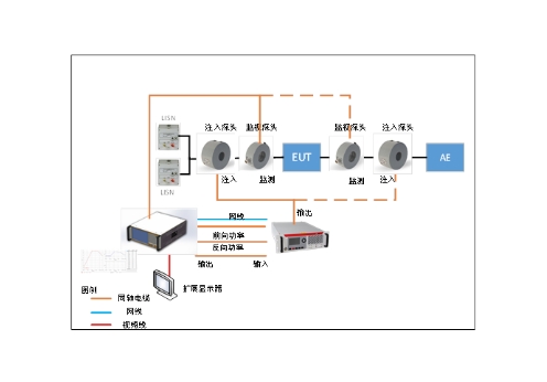
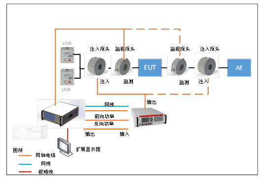
RF transmission immunity test system adopts integrated design, built-in integrated signal generator, RF power amplifier and RF power meter. Each device can be used independently, optional external power amplifier. The internal broadband power amplifier (Class A) drives the coupling/decoupling network (CDN), electromagnetic clamp (EM-clamp), and current clamp to obtain the test levels required by the standard. Test frequency range 4 KHz ~ 400 MHz, Meet the requirements of ISO 11452-4, IEC 61000-4-6, EN 61000-4-6, GB/T 17626.6, ISO 7637-4, GB/T 33014.4, GJB 151B-CS114, YY 0505 and other standards.
Integrated design Built-in integrated signal generator, RF power amplifier and RF power meter;
Support large current injection (with current injection clamp), optional current monitoring probe, support closed-loop test method;
Standard test procedures;
USB port for remote control on a PC.
Main technical parameters
Technical index:
Signal source parameters |
|
frequency range |
4kHz~400MHz |
power bracket |
-60dBm~+10dBm |
harmonic wave |
4kHz≤f≤100MHz <-35dBc |
|
100MHz<f≤300MHz <-30dBc |
|
300MHz<f≤400MHz <-27dBc |
anharmonic wave |
4kHz≤f≤100MHz <-50dBc |
|
100MHz<f≤300MHz <-55dBc |
|
300MHz<f≤400MHz <-49dBc |
AM modulate |
Adjustment system: 1%~99% |
|
Modulation frequency: 20 Hz ~ 20 kHz |
FM modulate |
Frequency deviation: 20 Hz ~ 100 kHz |
|
Modulation frequency: 20 Hz ~ 80 KHz |
PM modulate |
0~10 radian, Modulation frequency: 1 Hz ~ 20 kHz |
Pluse |
Pulse width: 100us~1s, pulse period: 200 uS ~ 2 S, off-off ratio> 40dB |
Spectrum analyzer parameters |
|
frequency range |
10Hz~1GHz |
RBW |
1Hz~250kHz |
Frequency accuracy |
1Hz |
DANL |
-110dBm@10Hz |
|
-130dBm@1GHz |
Input range |
DANL~10dBm |
Power amplifier parameters |
|
frequency range |
4kHz~400MHz |
power rating |
40 @4kHz~9kHz |
|
100 @9kHz~400MHz |
Harmonic formulation |
≤-13 @4kHz~9kHz |
|
≤-15 @9kHz~400MHz |
Power meter parameters |
|
frequency range |
4kHz~500MHz |
Power measurement range |
-65dBm~+10dBm |
The + 20 dBm is not damaged |
|
Probe matching |
|
Application for FCC, Solar, Montena, etc |
|
Standard compatibility |
|
GJB151B——CS114 |
|
GJB 1389A, GJB8848 conduction safety margin |
|
GB/T 17626.6、IEC61000-4-6,EN 61000-4-6 |
|
ISO 11452-4、ISO 11451-4 |
|
RTCA/DO-160G |
|
Note: Please note the test software function when placing an order |
|
Built-in embedded system, equipped with automatic test software, support for external screen expansion |
|
Volume and weight: 4U standard rack, 10kg |
|
Power supply requirements: 220V, 10A |