|
Waveform 1 wire harness test (short circuit impedance Z <0.1 Ω)
|
|
Set the range: 80-4000A, step into 1A
|
|
Maximum current: 4000A (+ 10%~0%)
|
|
Up time: 6.4 μ s ± 20%
|
|
Semi-peak width: 70 μ s ± 20%
|
|
Maximum voltage (open circuit): 3300V@4000A
|
|
Waveform 4 PIN foot injection (empty Z> 1000 Ω)
|
|
Up time: 6.4 μ s ± 20%
|
|
Semi-peak width: 70 μ s ± 20%
|
|
Set the range: 70-3200 V, step into 1V
|
|
Maximum voltage: 3200 V (+ 10% -0%)
|
|
Polarity: positive / negative / alternating
|
|
Waveform 4 PIN foot injection (short circuit Z <0.1 Ω)
|
|
Up time: 6.4 μ s ± 20%
|
|
Semi-peak width: 70 μ s ± 20%
|
|
Maximum current: 640 A@3200 V (Z = 5 Ω), + 10% -0%
|
|
Waveform 4 wire harness test (empty Z> 1000 Ω)
|
|
Set the range: 70-1700 V, step into 1V
|
|
Up time: 6.4 μ s ± 20%
|
|
Semi-peak width: 70 μ s ± 20%
|
|
Maximum voltage: 3200 V, maximum current of 6000 A (Z = 0.53 Ω) + 10% -0%
|
|
Waveform 5A PIN injection (no-load Z> 1000 Ω)
|
|
Rise time: 40 μ s ± 20%
|
|
Semi-peak width: 120 μ s ± 20%
|
|
Set the range: 70-3200 V, step into 1 V
|
|
Maximum voltage: 3200 V + 10% -0%
|
|
Polarity: positive / negative / alternating
|
|
Waveform 5A PIN injection (short circuit Z <0.01 Ω)
|
|
Rise time: 40 μ s ± 20%
|
|
Semi-peak width: 120 μ s ± 20%
|
|
Maximum current: 3200 A@3200 V (Z = 1 Ω) + 10% -0%
|
|
Waveform 5A, wire harness test (short circuit Z <0.1 Ω)
|
|
Set the range: 120-10000 A, step into 1 A
|
|
Maximum current: 10000A + 10% -0%
|
|
Rise time: 40 μ s ± 20%
|
|
Semi-peak width: 120 μ s ± 20%
|
|
Maximum voltage (open circuit): 1400 V @ 10000A
|
|
Waveform 5B PIN injection (no-load Z> 1000 Ω)
|
|
Rise time: 50 μ s ± 20%
|
|
Half-peak width: 500 μ s ± 20%
|
|
Set the range: 70-1600 V, step into 1 V
|
|
Maximum voltage: 1600 V + 10% -0%
|
|
Polarity: positive / negative / alternating
|
|
Waveform 5B PIN injection (short circuit Z <0.01 Ω)
|
|
Rise time: 50 μ s ± 20%
|
|
Half-peak width: 500 μ s ± 20%
|
|
Maximum current: 1600 A @1600 V (Z = 1 Ω) + 10% -0%
|
|
Waveform 5B wire harness test (short circuit Z <0.01 Ω)
|
|
Set the range: 150-5200 A, step into 1 A
|
|
Maximum current: 5000A + 10% -0%
|
|
Rise time: 50 μ s ± 20%
|
|
Half-peak width: 500 μ s ± 20%
|
|
Maximum voltage (open circuit): 500V @5000A (Z = 0.1 Ω)
|
 Solution
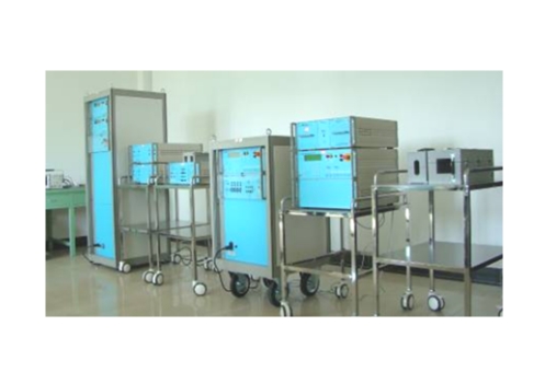
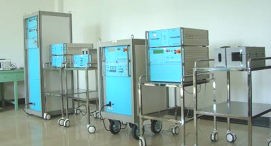
Lightning indirect effect system







 Record number: Su Gongwang Security 32011502021381