The low level method test system is mainly used to carry out the electromagnetic protection performance of the aircraft under the external HIRF environment, including the induced current of the wire harness at the connector end of the critical/important electronic and electrical equipment on board, and the field intensity near the installation area.
LLSC test uses the low-level analog signal equipment built in this system to irradiate the entire aircraft, and tests the coupling induced current of the wire harness of key equipment/system through the current probe. Compared with the calibration curve, the transfer function relationship between the electric field intensity irradiated by the radiation field and the induced current of the wire harness is obtained, and the induced current curve under the irradiation of high intensity radiation field is linearly extrapolated. The protection performance under the condition of high intensity radiation field is obtained by comparing with the corresponding level of the test system's conduction sensitivity limit curve.
LLSF test uses the low-level analog signal equipment built in this system to irradiate the aircraft cabin to be tested, and tests the field intensity value in the aircraft cabin through the receiving antenna or field intensity probe. Compared with the calibration curve, the attenuation characteristics (i.e., shielding performance) of each aircraft cabin can be obtained, and the field intensity curve of the aircraft cabin under the irradiation of high-intensity radiation field environment can be linearly extrapolated. Compared with the radiation sensitive limit curve of the measured system, the protection performance under the condition of high intensity radiation field is obtained.
 Solution
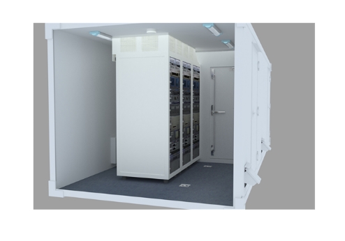
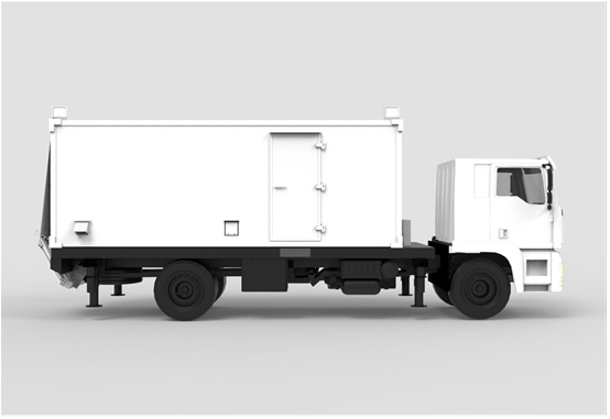
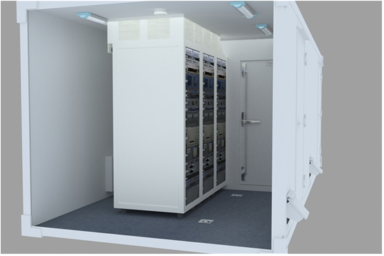
Low level method test system












 Record number: Su Gongwang Security 32011502021381