

 Product Center
Microwave active module

Microwave passive components

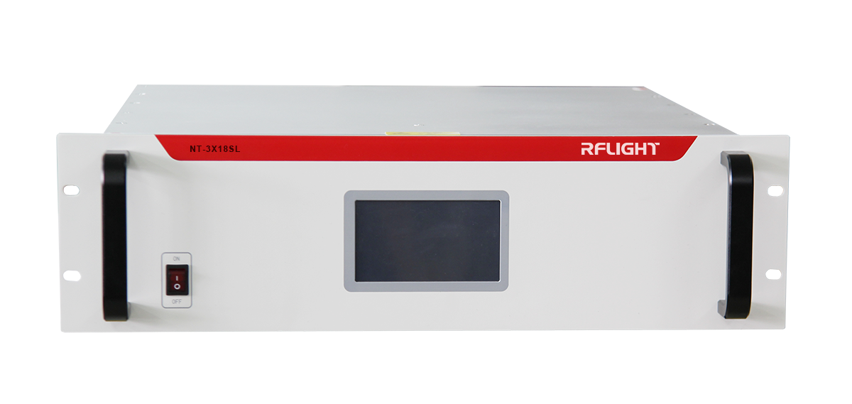
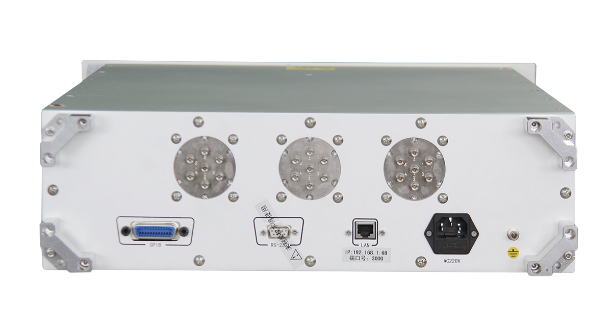
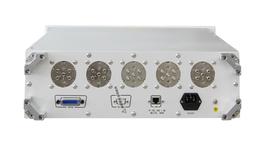
Power Amplifier

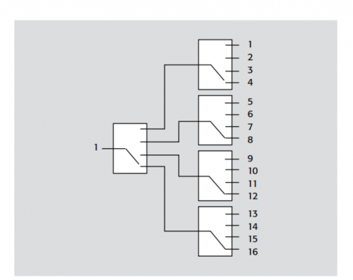
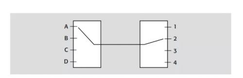
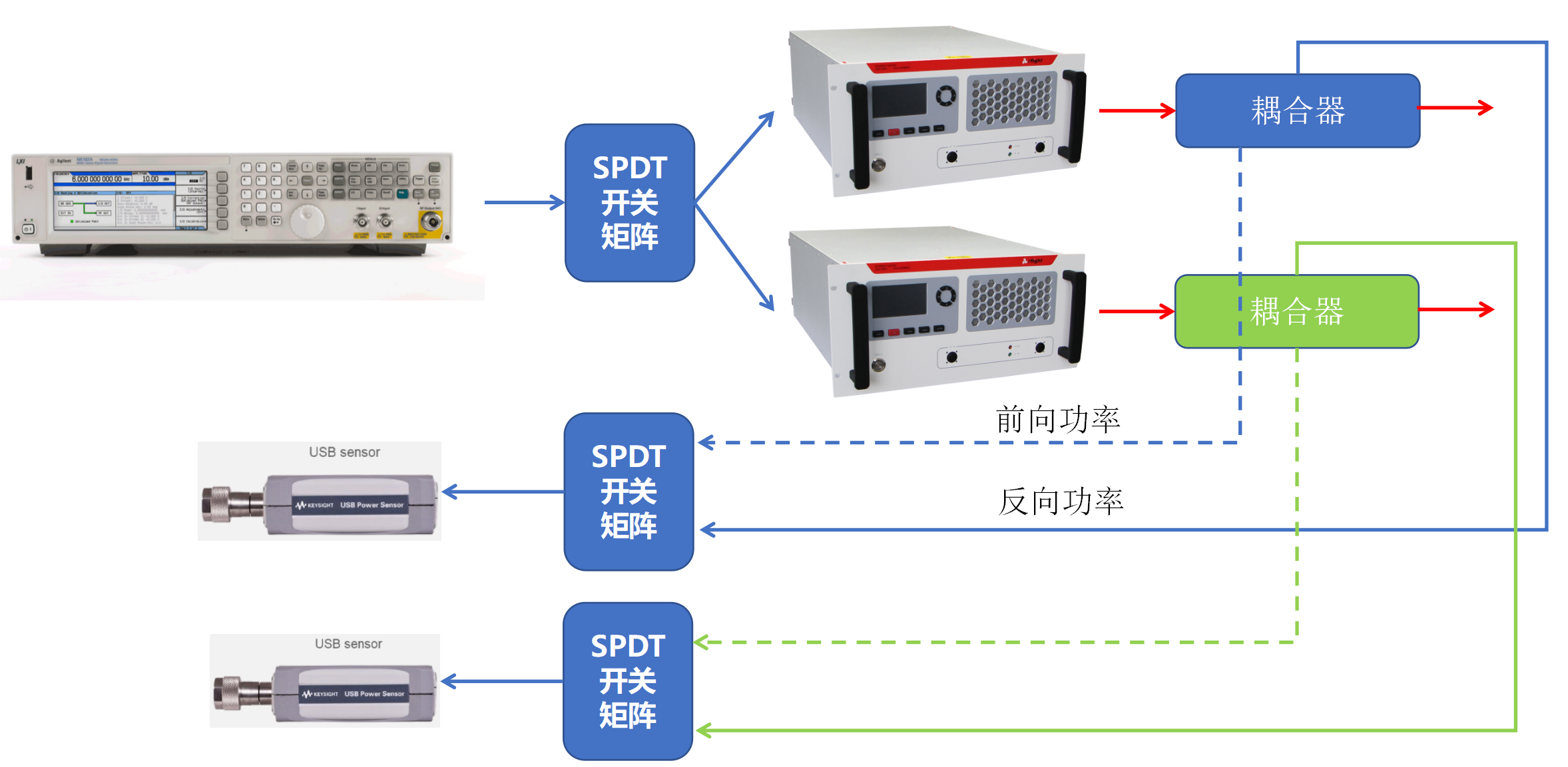
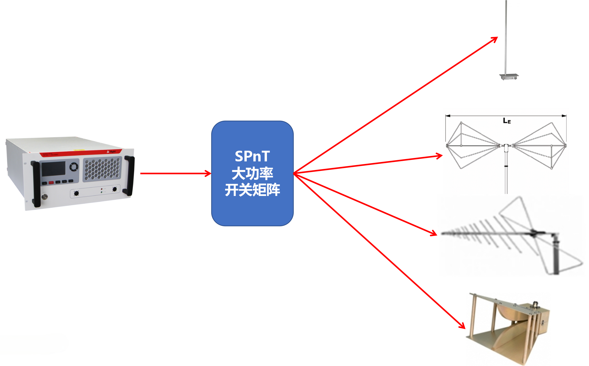
Rf matrix & Intermodulation test system

EMC testing system
High Intensity Radiation Field (HIRF) system

Integrated anti-drone system
Product Center


 Record number: Su Gongwang Security 32011502021381