Power Amplifier
High Intensity Radiation Field (HIRF) system
Electronic warfare simulation system
Intermodulation test system
Rf matrix system
Microwave active module
Passive device
Product Center
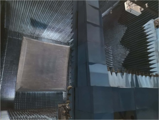
Example of a tight field test system
Compact field test system case
Summarize
The tight field system is a far-field test system, but the tight field can achieve better plane wave than the far-field in a shorter distance, and have better static area performance and dynamic range. The tight field system transforms the spherical wave generated by the point source into a plane wave within the near moment away, to realise the far-field test conditions required in the test and to obtain a better quality of the background level of the darkroom by focusing the electromagnetic wave beam.
The tight field system is mainly composed of reflecting surface system, feeder system, turntable system, RF link system and antenna darkroom system.
Client Name A well-known domestic communications equipment manufacturer
Main specifications of the test site:
Darkroom Dimensions:
13m*6m*6m
Frequency:
1700MHz-110GHz
Reflective surface size:
325cm*270cm
Static area size:
170cm*120cm
Amplitude taper:
≤1dB
Range:
±0.4dB
Phase taper:
≤5 degrees
Phase fluctuation:
±4 degrees
Cross-polarisation:
≤-30dB@typical
Typical frequency static area measured data — 1.7GHz,X cut
Amplitude fluctuation: 0.4 dB
Phase fluctuation: 1.4 °
Amplitude taper: 0.8 dB
Phase taper: 1.5 °
Cross-polarisation: ≤-32.0 dB
Typical frequency static area measured data — 2.6GHz,X cut
Amplitude fluctuation: 0.37dB
Phase fluctuation: 1.4 °
Amplitude Taper: 0.8dB
Phase Taper: 2.3 °
Cross-polarisation: ≤-31.0 dB
Typical frequency static area measured data — 33.5GHz,X cut
Amplitude fluctuation: 0.22dB
Phase fluctuation: 1.9 °
Amplitude Taper: 0.6dB
Phase Taper: 0.1 °
Cross-polarisation: ≤-30.0 dB